Posts

More hydroboost, Trying to buy batteries

Image
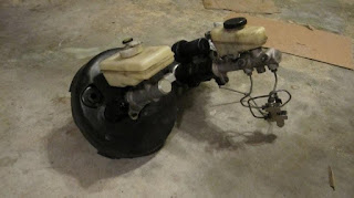
Progress is slow as my ICE powered cars are taking a bit of my time. Wife's maxima is crossing the 200K mark and decided it needed some maintance and repairs. But that's another story. I completed my adaptors to mount the Hydroboost into the car. Turned out rather well. I've been trying to purchase some batteries. I contacted the 2 battery dealers that were shown on the main website as closest to me. Asked them for their best price on 14 batteries and that I could come pick them up. It became very obvious that they have a HUGE margin on these products as they were more concerned about undercutting their other dealers AND making sure they were getting their commissions correct then they were in actually selling the product. In the end it seems they decided that my area is actually covered by a dealer in TN which is not even close to me and I won't be driving there to get them. Especially when I will be driving right by their north carolia store multiple times this month....

Hydrolic brake booster

Image
Not a ton of progress. Working on installing the hydrolic brake booster in place of the factory brake boster. The factory booster is the one with the larger dia cylinder on it (rh side on the pic on the right). The booster I am using is from a 97 Cobra mustang.

Batteries?

Thank you for the interest. Yes, with luck the hard part is over. We'll see how it goes from here. I don't think I mentioned the exact batteries as I'm still a little up in the air about which ones. Right now the needle is leaning toward Deka 9A31. It's an AGM battery with 100Ah. Thinking I might as well go with 156V the max voltage for the controller and use 13 batteries. I still do not feel confident I know enough about batteries but comparing the cost and weight of some similar batteries they seem pretty good. I still worry it won't be enough Ah as seems trying to predict the exact range is difficut. Guess I'll have to make a decision soon though.

EV comes inside

Image
With the rover out of the garage the electric car could FINALLY be brought in. Thought I'd take a couple pics of it first "drive" into the garage. I also loaded the motor and trans into the car. Still deciding on engine and trans placement. I'll probably go with the factory placement for the transmission but I have been toying with moving it back 8". Makes for a lot of extra room in the front. The driveshaft from an automatic car is 8" shorter than the manual car and bolts up so that would be no issue. However customizing the shifter seems like a big pain. My time is probably better spent elsewhere on the car. Other task was to remove the tank. This was actually quite easy. Remove the boot from the e-brake lever. Remove the nuts on the cables. Pull them out from under the car. Take out the three bolts holding the tank in and volia. After I had it out I found it still contained gas. I was under the impression it had been drained. So I pumped out 4 gallons ...

Other projects distract me

Image
Progress was delayed a bit as my rover needed some love. Here is the sparkly clean engine after re fitting the heads and rocker arms Of course a good helper is the key to a successful job (torquing the head bolts)

Motor Spinning the trans test

http://www.youtube.com/watch?v=zjhz9f9WXA8

Cutting the plate picture

Image
Here's a screen grab from the cutting process. I have it in movie form but it pretty much looks like the picture with the noise of the saw going I put the bolt holes into the transmission adapter plate by bushing the trans bolt holes with some thin metal then drilling through the bolt holes. Then enlarging them to the right size. On my trans the locating dowels are in the same location as a bolt hole so I drilled that through the bolt hole. Counterbored with the closest standard drill size to the dowel hole. Then used a rotary file (round dill bit like attachment with a flat bottom. Kind of like and end mill) in my drill to enlarge them slightly and I mean slightly enlarge the hole and cut a square edge at the bottom of the hole. Worked great. As others have done I then put the motor spacer plate on and the trans adapter plate and assembled them so they were against each other but not bolted together. I then spun the motor to center the trans. Drilled and doweled the two plates tog...

Motor adapter pictures

Image
Nothing really new to report. Just thought I'd add some pictures since pictures are fun. Notice how close to the trans I mounted the motor. The larger plate is .5" thick and the smaller one about the dia of the motor is 5/8" thick. No modifications to the transmission side were required. The extra space may not matter. Have to see but either way a thinner spacer is lighter. By the way I cut out the plates myself (exception being the precision hole in the motor spacer plate) using a simple hand jigsaw and an with an aluminum blade. What I thought made it go well was to pour water on the blade/plate to keep things cool. To do the motor spacer plate I'd say it took just under an hour and a gal or so of water.

Adapter Plate DONE!

Image
Update. I reassembled the transmission and I cut out my adapter plates. The trans now mounts to the engine and spins without the rock crusher sound Thinking seriously about mounting it into the car. Adapter plate cut out Assembled Stacked and bolted

Zilla Arrives

Image
Ok after about 8 months of waiting it arrived!! The zilla's here. Pretty exciting. Surprisingly I didn't just tear open the boxes. I had a Sim racing league race that evening so i just put them aside. However as fate would have it my computer hiccuped after qualification and I wasn't able to race. So I opened the boxes and basked in the glory of having more EV parts. Let's re-live the box opening for those that haven't done it. Here is what it looks like when it arrives. Just Like Christmas. In side the box is 2 smaller boxes. The controller in one and the hairball and cables in the other. Of course included is the handy dandy notebook...or manual. I also purchased the hall effect pedal (in it's own box) so I can do the full drive by wire. Here it all is right before I reboxed to put on the shelf. . Guess I need to get to work on it all again.

2nd gear "removed"

Image
Progress is slow at the moment. Amazing how much time earning a living and raising a family can take. Oh and I joined an online Sim racing league (again) . That didn't help. My EV project is a hobby anyway. The sooner it's done the sooner I'll be thinking of some other project. Not much to report except I did grind the teeth off 2nd gear. Didn't really take that long. Used a thin cutting wheel on my angle grinder to cut off most of the teeth. Kind of like cutting the kernals of corn of corn on the cob. Then I took a grinding wheel to it make it mostly round. Here's a before and after picture. Took about 30 min. Wife said the sparks were more impressive than the firework fountains we usually buy for the 4th of july

Trans is damaged

Image
EV construction has been slowed for some Tramission issues. I've gotten the transmission apart. The trans that "worked fine just needed a rebuild" is missing many teeth on 2nd gear. This trans is basically beyond repair. I wish it had been 1st gear as I probaby don't need 1st gear. The way it was the trans sounded like it was crunching gravel. No suprize there. For now I'm thinking I'll grind off ALL the 2nd gear teeth and just go without a 2nd gear. May not need it so much. I can get another transmission later. We'll see. I think finish my adapter plate and then decide.
Image
UPDATE: When I spun the trans with the motor the transmission sounded like it was full of rocks. I was told it made a "rattle" when I bought it. I figured it just needed new bearings but this was a much more than a rattlle. Either way the trans needed to come apart so apart it came. Turns out there are many teeth broken off 2nd gear. Too bad it wasn't first gear as it that doesn't seem to be needed in and EV. I'll spend some more time practicing rebuilding this transmission as with a car of this age the next trans I buy will likely need some rebuilding too.

Mate motor to trans

Image
Did a little more work. Mated the trans to the motor. Have some more trimming to do on the adapter plate (or plates depending on how you look at it). I mounted one plate to the motor and one to the trans. With the trans setting on the motor and the input shaft engaged with the clutch I spun the motor and centered or checked to ensure it was centered prior to pining the 2 plates together. One thing I found was the clutch alignment tool would align the clutch disc so the trans could be installed but it was not truely centered. So I used the dial indicator to center the clutch plate prior to putting on the pressure plate. This turned out perfectly. Couple of pictures. The taper lock installed on the motor Transmission on top of the motor.

More on the motor flywheel adapter.

Image
For this project I found some software to download for FREE (Alibre Design) that is ALMOST as good as what I used at work back then. Edit. Alibre Design sucks. They said it was free but then a few months later disallowed usage of the program. SO now my documents are drawn in a program I can't use. I DO NOT recommend it. As far as the wild machining. All the center features were as purchased (it started life as a taper lock sprocket). The blind tapped holes aren't too difficult. Well being the holiday I had some time to work on things. Turned down the OD of my pilot bushing myself. Seems they don't make a 15mm ID bearing with the OD to fit the Warp 9 motor. So I started with a Mcmaster carr HPF bushing (6659k28) and reduced the outside to about .001 over the bore dia of the hole in the motor. Well I first tired .010 over but when I pressed the bushing in it shrank the ID. The bushing was only a $1.50 so I had bought 2. good thing. Try 2 was successful and I now hav...

Parts back from the machinist.

Image
My Flywheel adapter and one AL plate came back from the machinist today. I love seeing the parts turn from Cad into Real life. The adapter looks like it will work out exactly as planned. I have bolted it to the flywheel and slid it onto the motor shaft. I'll check it to see if it turned out true and straight and then I can go on to making the transmission plate. Here ae a couple pics. Below is the adapter setting in the back of the flywheel
Image
Here's and update. Holidays and my online racing season have been keeping me busy. But above is a picture of the the taper lock sprocket and taperlock bushing I purchased to use in my flywheel adapter (finally got around to ordering). Also pictured is an aluminum plate I'll use for part of the motor spacer, a bronze bushing I'll use as the pilot bushing (have to alter the OD slightly) and some keystock. Dropped the Taperlock off at the machinist today. Should be a week or so until I get that back. I'm anxious to bolt the flywheel to the motor.

Purchase Chassis "donor car"

Image
I picked up a chassis for the swap and at the same time got a ride in Ben's ("TelnetManta's") EV saturday. Here's a pic of me pulling the BMW home with the land rover. Incidently I had just rebuilt the land rover's auto trans myself. After that experience I really have no interest of an auto trans in my EV....Or any other car for that matter.

Motor adapter redesign

Image
Here is my flywheel adapter redesigned to use a 1610 taper-lock and Modified Taperlock sprocket. I plan to install the taper lock with the setscrews facing the motor so the clutch pressure will press the adapter on tigher instead of trying to pull it off. The other big change is since the center of the sprocket is larger dia then the pilot of the flywheel I plan to use 2 dowels to locate the flywheel on the adapter. (one is in the flywheel from the factory. I'll have to add the other). I also plan to put a bushing/spacer between the motor and taperlock so the clutch force can push the assy forward. Anyway I have attached a 3D screen shot and a drawing of the adapter for your review Parts below Purchased from McMaster Carr Taper-lock Bushing- Bore Steel Sprocket # 60: 2590K83 Taper-lock Bushing, Size 1610 1-1/8 bore: 57095k164 Aluminum Plate (6061) 5/8 x 12 x12": 8975K159
Image
I also hooked it up to my battery charger and ran it for a few min. It was nice and quiet. Quite satisfying to see/hear it spinnig. While I was at it I stood it on end and set the trans on top of it to ensure I have my dimensions correct for my adapter plate thickness. Thick enough to keep the trans input shaft from bottoming out but not too thick to have it not engage the end of the motor shaft. Looks like 1.125 thick is going to work great. Here is a pic of my measuring set up. 2 pieces of angle bolted to the motor then some spacers (happen to be sockets in my case) of the right length.

Warp9 Arrives

Image
Monday the Warp 9 motor arrived. Today my aluminum flywheel arrived. Parts are starting to roll in Here is the motor as delivered infront of my V-8 powered 3 series. Here is how it was packaged. Looked pretty safe and un harmed. Some initial inspection shows that someone at the factory ran a razer knife or something similar down the larger drive shaft like they were cutting a tag off it or something. Left a pretty good scratch but It can be buffed out. No pic of the flywheel yet. I did some reading and decided that a taper-lock hub is probably the way to go. So I have to redesign my flywheel to motor attachment. Back to the drawing board

Transmission adapter begins.

Image
Been awhile so time for an update. While waiting for the long lead time EV parts (controller and motor) I have been shoping for a donor car. Just about bought one last weekend. After realizing the only thing I needed it for was to remove the engine and make the motor adapter I choose to just buy a transmision instead. This way I don't have another whole car hanging about the place for months while I just wait for parts. Of course if the right donor car pops up I'll grab it but until then I have something to work with. So with that in mind I started working on a adapter to adapt the WarP 9 motor to the BMW flywheel. First thing I found was the JPG drawing of the warp 9 is pretty much illegible from the netgain site. Oh well I could make out what I needed. I'm plaining to make the adapter out of a sprocket with the ID bore and Keyway dimensions required to fit the motor. Will save on some machining. I sketched it up on paper but would rather have a cad drawing. I downloaded a...

Waiting for parts......

I got notification that the motor will ship sometime in early October. Glad I'm not in a hurry because the controller will take even longer. Sadly I haven't even heard as much as boo from Cafe electric on a projected date. From what I gather from everyone else I should be expecting just in time for christmas

P/S Pump Arives

Image
Well a little new news on the EV front. My powersteering pump arrived. Here's a picture for those that need a visual fix. The other big news is I ordered my motor today. Went with the WarP 9" as previously outlined. Been shoping for cars too. I really don't need the car until I get all the parts collected but if the perfect one was to pop up.... I've been looking at batteries. I'm thinking I need about 1,000 amp hrs worth.

Ordered P/S pump

I ordered a 2001 MR2 which from what I understand is less used by people for swaps. Cheaper and more available at the moment. Since I'm collecting parts and waiting for the zilla I have plenty of time to sort out the differences with the different style pump.

Clutch vs Clutchless

Not much to show at the moment . Just have the longest lead time item on order. Well after careful consideration I believe I made my decision on the Clutch Vs Clutchless. Though I believe the clutchless would work it all came down to this.......My wife. She will be driving the car as well. Her daily driver is a manual and if she is switching back and forth between the electric and she gets used to shifting with no clutch and goes back to her manual trans ICE powered car... I think you know where I am going with this.

Beginning Summary

Not much yet but I placed my order or rather "secured my place in line" for a zilla controller so I guess the project is started. I was just excited to actually do something more than just talk about this project. Sadly it isn't much but it is something. In the sticky it recommends sharing: Your skill level with auto mechanics and fabrication I do all my own auto repairs. I have a welder and I can do basic welding. I'm good with automotive wiring but am not an electrical expert. I have done 2 Gas engine swaps into cars that the engine/trans was never designed to go (check out LS1BMW.blogspot.com). The mechanical part of this project, building battery trays coupling the motor to the trans etc, sound like fun. I may have to copy and rely on some others for the electrical component expert advice. The range you are hoping to get (how many miles/charge) I'm going for 20 to 25 miles per charge. My round trip to work is 18miles (slightly hilly). Anything past that is bon...

Flywheel musings

Reducing rotational mass is benficial in EV's just like in ICE's. What's even better in EV's is there no issue with the car being unable to idle or launch from a stop . I'm using an aluminum flywheel designed for the 318 (smaller dia than 325 or M) and an unsprung clutch disc. The metal ring gear on the AL flywheel is a bolt on and I'll remove this a little later as well. I bought the flywheel and clutch disc used and in good condition for $100 off e-bay. For that much I figured it was worth it. To get something with less rotational mass could go to a racing multiplate clutch and AL flywheel and turn off the ring gear. Would have more holding power and less rotational mass. I looked into it but the prices were crazy.