Posts

More on the motor flywheel adapter.

Image
For this project I found some software to download for FREE (Alibre Design) that is ALMOST as good as what I used at work back then. Edit. Alibre Design sucks. They said it was free but then a few months later disallowed usage of the program. SO now my documents are drawn in a program I can't use. I DO NOT recommend it. As far as the wild machining. All the center features were as purchased (it started life as a taper lock sprocket). The blind tapped holes aren't too difficult. Well being the holiday I had some time to work on things. Turned down the OD of my pilot bushing myself. Seems they don't make a 15mm ID bearing with the OD to fit the Warp 9 motor. So I started with a Mcmaster carr HPF bushing (6659k28) and reduced the outside to about .001 over the bore dia of the hole in the motor. Well I first tired .010 over but when I pressed the bushing in it shrank the ID. The bushing was only a $1.50 so I had bought 2. good thing. Try 2 was successful and I now hav

Parts back from the machinist.

Image
My Flywheel adapter and one AL plate came back from the machinist today. I love seeing the parts turn from Cad into Real life. The adapter looks like it will work out exactly as planned. I have bolted it to the flywheel and slid it onto the motor shaft. I'll check it to see if it turned out true and straight and then I can go on to making the transmission plate. Here ae a couple pics. Below is the adapter setting in the back of the flywheel
Image
Here's and update. Holidays and my online racing season have been keeping me busy. But above is a picture of the the taper lock sprocket and taperlock bushing I purchased to use in my flywheel adapter (finally got around to ordering). Also pictured is an aluminum plate I'll use for part of the motor spacer, a bronze bushing I'll use as the pilot bushing (have to alter the OD slightly) and some keystock. Dropped the Taperlock off at the machinist today. Should be a week or so until I get that back. I'm anxious to bolt the flywheel to the motor.

Purchase Chassis "donor car"

Image
I picked up a chassis for the swap and at the same time got a ride in Ben's ("TelnetManta's") EV saturday. Here's a pic of me pulling the BMW home with the land rover. Incidently I had just rebuilt the land rover's auto trans myself. After that experience I really have no interest of an auto trans in my EV....Or any other car for that matter.

Motor adapter redesign

Image
Here is my flywheel adapter redesigned to use a 1610 taper-lock and Modified Taperlock sprocket. I plan to install the taper lock with the setscrews facing the motor so the clutch pressure will press the adapter on tigher instead of trying to pull it off. The other big change is since the center of the sprocket is larger dia then the pilot of the flywheel I plan to use 2 dowels to locate the flywheel on the adapter. (one is in the flywheel from the factory. I'll have to add the other). I also plan to put a bushing/spacer between the motor and taperlock so the clutch force can push the assy forward. Anyway I have attached a 3D screen shot and a drawing of the adapter for your review Parts below Purchased from McMaster Carr Taper-lock Bushing- Bore Steel Sprocket # 60: 2590K83 Taper-lock Bushing, Size 1610 1-1/8 bore: 57095k164 Aluminum Plate (6061) 5/8 x 12 x12": 8975K159
Image
I also hooked it up to my battery charger and ran it for a few min. It was nice and quiet. Quite satisfying to see/hear it spinnig. While I was at it I stood it on end and set the trans on top of it to ensure I have my dimensions correct for my adapter plate thickness. Thick enough to keep the trans input shaft from bottoming out but not too thick to have it not engage the end of the motor shaft. Looks like 1.125 thick is going to work great. Here is a pic of my measuring set up. 2 pieces of angle bolted to the motor then some spacers (happen to be sockets in my case) of the right length.

Warp9 Arrives

Image
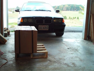
Monday the Warp 9 motor arrived. Today my aluminum flywheel arrived. Parts are starting to roll in Here is the motor as delivered infront of my V-8 powered 3 series. Here is how it was packaged. Looked pretty safe and un harmed. Some initial inspection shows that someone at the factory ran a razer knife or something similar down the larger drive shaft like they were cutting a tag off it or something. Left a pretty good scratch but It can be buffed out. No pic of the flywheel yet. I did some reading and decided that a taper-lock hub is probably the way to go. So I have to redesign my flywheel to motor attachment. Back to the drawing board