Posts

Test the clutch and drive line

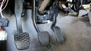
Got the clutch working today. Apparently to bleed this clutch system the slave cylinder has to be removed from the trans and tilted to have the bleed valve up. Weird. Did that and the clutch now works. Am behind on ordering things. Lugs and welding equiptment for welding aluminum are finally now on order. Looking at what guages I needed and found that the zilla will Display motor current on the tach. Interesting. Do I even need a battery current Ammeter? I think for now I'll go sparse on guages and add later but before it hits the road. My Goal right now is to put it together enough it'll drive in and out of the garage. So a lot of the guages and such can wait. Next steps will be: 1. Make front battery trays 2. Mount Controller and wire up hairball 3. Wire up front batteries Ok you tube is done. Video is http://www.youtube.com/watch?v=YiOYDu8Rk3M

Motor mount done

Image
Well here is the motor mount. It attaches to the 2 side bolts on the motor and 2 of the front bolts. I'm attaching it to the crossmember using using 2 existing holes. I used 2 rubber transmission mounts instead of motor mounts as they are smaller and this motor is lighter than the gas engine. I also didn't go with the ICE engine motor mounts and locations as I wanted to leave room on the side of the motor for another battery. I think it turned out well. Location is good being Dead center and level. Oh wire arrived today. Looks nice and beefy (4/0) and is quite flexible. I need to select and find a place to buy the fuse, circuit breaker and shunt. The motor mount I think will work out great. I am a mechanical engineer and use to design weldments as a job years ago. Did not do any analysis on this structure, other than rough numbers for the force that'll be applied at the mount points, but it should be plenty strong. And small is light and more room for the batteries. Oh

misc.

I was looking around and found some tinned lugs with the right bolt hole in them for a reasonable price. Think I'll just order them. I have my motor mount bracket just about done. Painted it last night. will have to get some pictures and post it. Went a little different way than what I have seen most do.

Order Main Wiring

I ordered the main wiring. After some reading I realized that 4/0 wiring is probably overkill and should buy 2/0. Cost difference would probably be about $100. Then I thought to myself.....if this were a gas car and I could get a few HP for an extra couple of bucks would I do it? Sure I would. Ordered 4/0 wire. I also ordered a hammer crimper. I have a hydrolic press so I'm thinking I can just put it in the press instead of whacking at it with a hammer. I haven't ordered any lugs. I'm wondering if I can make some out of some copper tube. Prices seem to be a ripoff and I didn't see any with the through hole I needed. I'll give it a go after the wire arrives. Manged to get a battery in my fuel tank location battery rack. I was able to test the clearances in the front and rear location. Looks like it'll work out great. Getting it up there with the batteries in it is going to be a trick but I'll worry about that when I get that far. I'm sure it can be done.

Gas tank battery rack

Image
Finally had a saturday where I wasn't travelling, there wasn't another car repair I had to do, the kids didn't have a scoccer game etc. so I got some work done on the EV. I'd really like to get it so it'll move under it's own power so I can move it out of the garage during the week. Started on the gas tank location battery rack. Made some good progress so far. Here's a pict in the middle of construction.

HEPA pedal install, Brake fluid reservior relocation

Image
Installed the Hall effect sensor Pedal. I keep wanting to call it a GAS pedal but obviously that's not right. My boy keeps correcting me with "Accelerator" pedal. Pic attached of the pedal installed. Have also connected the wire. I reused the firewall fitting/gromet that the cable had used. Just drilled it out a bit larger for a nice snug fit on the wire. Makes for a nice clean installation. I also finished the high pressure and low pressure brake fluid lines. The 92-95 BMW's had low pressure brake fluid lines going from the fluid reservior to the ABS unit (see the picture). So I did a remote mount of the BMW fluid tank to the Mustang master cyl and ran new lines to the ABS. Doing some research I found that EPDM style rubber hoses are recommended for use with brake fluid. Looking around locally I found that hose made for farm fertilizer etc sprayers are made of the same thing. So I got some at tractor supply. So far it looks like it will work good. The metal for mak

More P/S information

Image
Forgot to mention that on the MR2 pump I realized that the reservior could be rotated so that the return fitting could point another direction. However the bump on the inside of the reservior hits on some of the parts of the pump. I took off the plastic reservior and took a picture. See attached. So you get a better idea of what I'm talking about. So to orient the outlet at a very different angle it may require removing the reservior turning to the direction and refitting. sadly there are a few angles where it just can not be placed but that's not to big of a deal. Also shown is the braided steel hose and fittings I used to make the custom AN style High pressure lines. Like what is common on race cars. It is easy enough to do. In my set up I have one line going from the PS pump to the hydro boost and one from the hydro boost to the P/S Rack. I need to finish the return lines then I could give the hydrolics a try. Adapter fittings purchased from pegusus parts www.pegasusautorac